几何对象
在 环境搭建一节中,我们已经完成了环境设置,本节将介绍AnyCAD三维控件中两个最基本的概念:几何拓扑对象和几何显示对象。
1. 几何拓扑对象
几何拓扑对象是从数学上精确描述物体的形状。
比如在XOY平面上创建一个30 X 40、圆角半径位5的矩形,我们可以先创建矩形的拓扑对象,如下:
    TopoShape rect = CurveBuilder.MakeRectangle(GP.XOY(), 30, 40, 5, false);

    // 显示出来
mRenderView.ShowShape(rect, ColorTable.Green);1.1 TopoShape
TopoShape 表示几何拓扑对象,可以是顶点、边、面、体、复合体等,采用边界表达(Boundary Representation,BREP)方式描述物体的几何结构。
在实体建模和计算机辅助设计中,边界表示法(通常简称为B-rep或BREP)是一种利用边界来表示形状的方法。实体被表示为一系列相互连接的表面元素的集合,这些元素构成了实体与非实体之间的边界。
模型的边界表示由两部分组成:拓扑结构和几何形状(表面、曲线和点)。主要的拓扑元素包括:面、边和顶点。面是表面的一个有界部分;边是曲线的一个有界段;顶点位于一个点上。其他元素包括壳(一组相互连接的面)、环(构成面的边的回路)和环边链接(也称为翼边链接或半边),它们用于形成边的回路。这些边就像桌子的边一样,界定了一个表面部分。
几何对象分为平面的几何对象和三维的立体对象,分别使用CurveBuilder和ShapeBuilder来创建。
1.2 CurveBuilder
CurveBuilder 包含了常见的三维平面基本体对象创建方法,包括点、直线段、圆弧曲线、长方形、多边形、BSpline等。
1.3 ShapeBuilder
ShapeBuilder 包含了常见的三维立体对象的创建方法,包括球体、长方体、圆柱体、圆锥、管子等。
1.4 试一试
调用CurveBuilder和ShapeBuilder创建一下常见的平面图形和立体图形。

2. 几何显示对象
现在的底层图形API,如OpenGL和DirectX,只能绘制的几何图元有:点、线段、三角形面片三大类。数学上描述的几何对象(TopoShape)不能直接被显示引擎消费,因而需要转换成显示引擎可消费的几何显示对象。
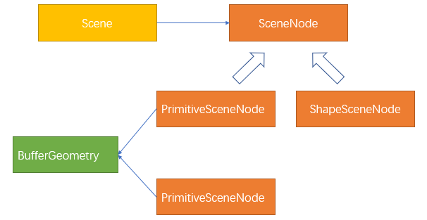
AnyCAD显示引擎底层使用BufferGeometry来描述基本图元:点、线段、三角形面片。
为管理显示场景中众多的绘制对象,显示引擎普遍采样场景树来组织和管理显示对象,如场景八叉树、KD树等。 AnyCAD显示引擎使用SceneNode来表示场景节点,结合GroupSceneNode可以设计任意的场景树。
上述显示矩形的代码中,RenderControl.ShowShape方法内部会通过GRepShape把TopoShape转换成BufferGeometry对象,挂接到场景节点BrepSceneNode对象上,添加到场景Scene中才能显示。引用关系如下:

GRepShape跟TopoShape是一一对应,但同一个GRepShape可以放在不同的BrepSceneNode中。因此,具有相同形状的几何对象,但位置不一样的话,可以利用这个机制实现实例绘制。

示例,使用实例技术快速创建1000个球:
var shape = ShapeBuilder.MakeSphere(new GPnt(), 1);
var grep = GRepShape.Create(shape, null, null, 0.5, true);//可以自己指定显示精度
grep.Build(); // 初始化

float distance = 3.0f;
int halfCount = 5;

var scene = mRenderView.Scene;
for (int ii = -halfCount; ii < halfCount; ++ii)
    for (int jj = -halfCount; jj < halfCount; ++jj)
        for (int kk = -halfCount; kk < halfCount; ++kk)
        {
            var node = new BrepSceneNode(grep);
            // 通过矩阵变换设置绘制对象的位置
            node.SetTransform(Matrix4.makeTranslation(ii * distance, jj * distance, kk * distance));
            // 加到场景中
            scene.AddNode(node);
}2.1 BufferGeometry
BufferGeometry描述了可以用于显示的图元,包括点、线段、三角网格(Mesh)。TopoShape本质上是转成了BufferGeometry才显示的。
BufferGeometry挂接到PrimitiveSceneNode上后,添加到场景中便可显示。

TIP
使用BufferGeometry可以描述任意形状的物体(点、线、面)。可以使用自己的顶点、法线、纹理贴图坐标等信息构造显示对象。
2.2 GeometryBuilder
通过TopoShape可以间接创建显示对象,也可以使用GeometryBuilder直接构造BufferGeometry。 如果只是创建展示用的几何对象,建议使用GeometryBuilder来创建,不仅效率高,还更节省内存。
GeometryBuilder封装了快速创建显示基本体,包括Box、Sphere、Cylinder、Plane等。
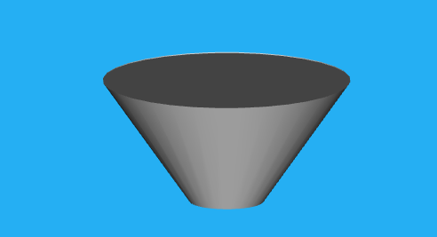
示例:创建一个圆台
    // 构造形状
    var geom = GeometryBuilder.CreateCylinder(10, 3, 10);
     // 设置为灰色
    var materail = mRenderView.GetMaterial(ColorTable.LightGray, 0);
    var cylPrim = new PrimitiveSceneNode(geom, materail);
    // 设置位置
    cylPrim.SetTransform(Matrix4.makeTranslation(-30, 0, 0));
mRenderView.ShowSceneNode(cylPrim);效果如下:

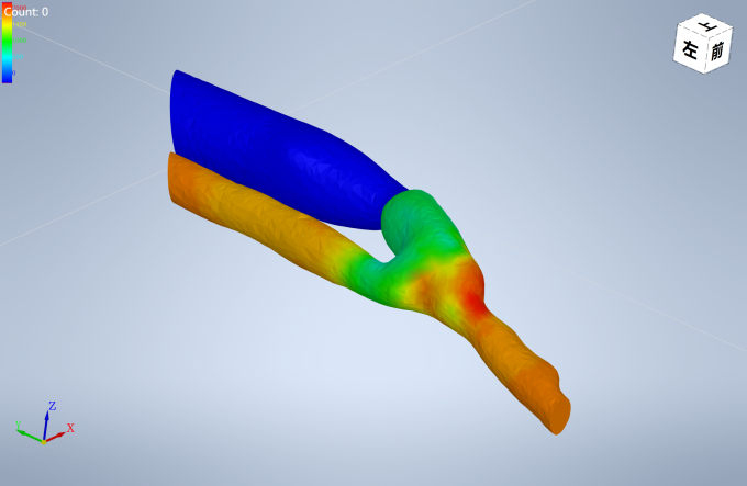
使用显示对象可以实现CAE应用中常见的云图效果:

3 小结
本小结简单介绍了创建几何对象TopoShape和显示对象BufferGeometry,以及如何通过SceneNode把几何对象和显示对象挂接到场景中显示。
4 思考问题
- 几何对象和显示对象的区别和联系是什么?
- 显示对象的应用场景是什么?
- 几何对象的应用场景是什么?